Ever wondered how complex machinery, from factory assembly lines to your refrigerator, operates so seamlessly? The answer often lies in a fascinating language of symbols – electrical, pneumatic, and logic symbols. These visual representations form the backbone of control systems, allowing engineers to design, understand, and troubleshoot automated processes.
Imagine trying to explain a complex electrical circuit using only words. It would quickly become a confusing mess. That's where electrical symbols come in. They provide a concise and universally understood way to represent electrical components like switches, resistors, and motors. Similarly, pneumatic symbols depict components used in systems powered by compressed air, while logic symbols represent the logical operations that govern control systems.
The history of these symbols is intertwined with the development of industrial automation. As systems became more complex, the need for a standardized language became apparent. Organizations like the International Electrotechnical Commission (IEC) and the American National Standards Institute (ANSI) played crucial roles in developing and standardizing these symbolic representations. This standardization ensures that engineers across the globe can interpret diagrams and collaborate effectively.
Understanding these symbols is paramount for anyone involved in designing, operating, or maintaining automated systems. They provide a blueprint for how the system functions, allowing engineers to troubleshoot problems efficiently and make modifications as needed. Misinterpreting a single symbol can lead to malfunctions or even safety hazards, highlighting the importance of accurate and consistent usage.
A key issue related to these symbols is the potential for variation and misinterpretation. While standards exist, there can still be subtle differences in how symbols are represented. This can lead to confusion, particularly when working with older diagrams or systems from different regions. Therefore, careful attention to detail and referencing appropriate standards is crucial.
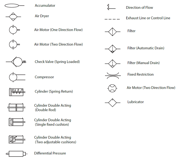
Electrical symbols represent elements like batteries, transformers, and wires. Pneumatic symbols depict components like valves, cylinders, and compressors, using specific shapes to indicate their function. Logic symbols use shapes like AND gates, OR gates, and NOT gates to represent logical operations that dictate the flow of information within the system.
These symbols provide numerous benefits. Firstly, they promote clear communication and understanding among engineers and technicians. Secondly, they simplify complex designs, making them easier to analyze and troubleshoot. Thirdly, they facilitate efficient design and modification of control systems, saving time and resources.
Creating an effective control system involves several steps. First, identify the desired system behavior. Then, develop a logic diagram using appropriate symbols. Next, select the corresponding electrical and/or pneumatic components. Finally, test and refine the system to ensure it operates as intended.
Advantages and Disadvantages of Standardized Symbols
| Advantages | Disadvantages |
|---|---|
| Clear Communication | Potential for Variation |
| Simplified Designs | Requires Training and Familiarity |
| Efficient Troubleshooting | Can be Overwhelming for Beginners |
Best practices include using standard symbols, labeling diagrams clearly, and maintaining consistent documentation. Real-world examples include conveyor belt systems, automated packaging lines, and robotic welding cells.
Challenges can include outdated symbols, software compatibility issues, and the need for ongoing training. Solutions involve adopting current standards, utilizing compatible software, and providing regular training programs.
Frequently asked questions often pertain to specific symbol meanings, software recommendations, and troubleshooting tips.
Tips and tricks include using online symbol libraries, practicing diagram creation, and seeking guidance from experienced engineers.
In conclusion, electrical, pneumatic, and logic symbols are essential tools for anyone working with control systems. They provide a powerful language for designing, understanding, and maintaining complex automated processes. By mastering these symbols and adhering to best practices, engineers can create efficient, reliable, and safe systems that drive modern technology. The consistent use of these symbols enables clear communication, reduces errors, and streamlines the entire engineering process. As automation continues to advance, the role of these symbols will become even more critical in shaping the world around us. Investing time in learning and understanding them is an investment in the future of engineering.
Conquering the one inch nut your wrench size guide
Navigating legal waters with payne perkins law group
Unlocking the power of behrs top neutral paint hues


