Imagine trying to build a complex Lego castle without the instructions. Frustrating, right? That's what designing or troubleshooting an electrical circuit would be like without a standardized system of symbols. These little icons, seemingly simple scribbles, are the language of electronics, enabling engineers and hobbyists alike to communicate complex ideas in a universally understood way. But how did these symbols come to be, and why are they so crucial?
Electronic and electrical diagrams are essentially roadmaps for electricity. They depict how current flows through a circuit, showing components like resistors, capacitors, and transistors. These graphical representations rely heavily on standardized symbols, making it possible to convey the intricacies of a circuit without lengthy, confusing written descriptions. Imagine trying to explain the wiring of your house using only words. The task would be monumental. With symbols, the same information can be conveyed concisely and effectively.
The history of electrical symbols is intertwined with the development of electricity itself. As early experimenters started to tinker with batteries, wires, and other components, they needed ways to represent their creations. Initially, drawings were often realistic, depicting actual batteries and other devices. Over time, these depictions evolved into more abstract symbols, driven by the need for simplicity and standardization. The growth of the electronics industry in the 20th century further solidified the importance of standardized symbology, leading to international standards like those established by the IEC (International Electrotechnical Commission).
The significance of using consistent electrical and electronic symbols cannot be overstated. These symbols aren't just convenient shorthand; they are the foundation of clear communication in the field. They allow engineers from different countries, speaking different languages, to collaborate on projects without the barrier of language. This universality is critical for safety, efficient design, and effective troubleshooting. Misinterpreting a symbol could lead to a faulty circuit, malfunctioning equipment, or even dangerous electrical hazards.
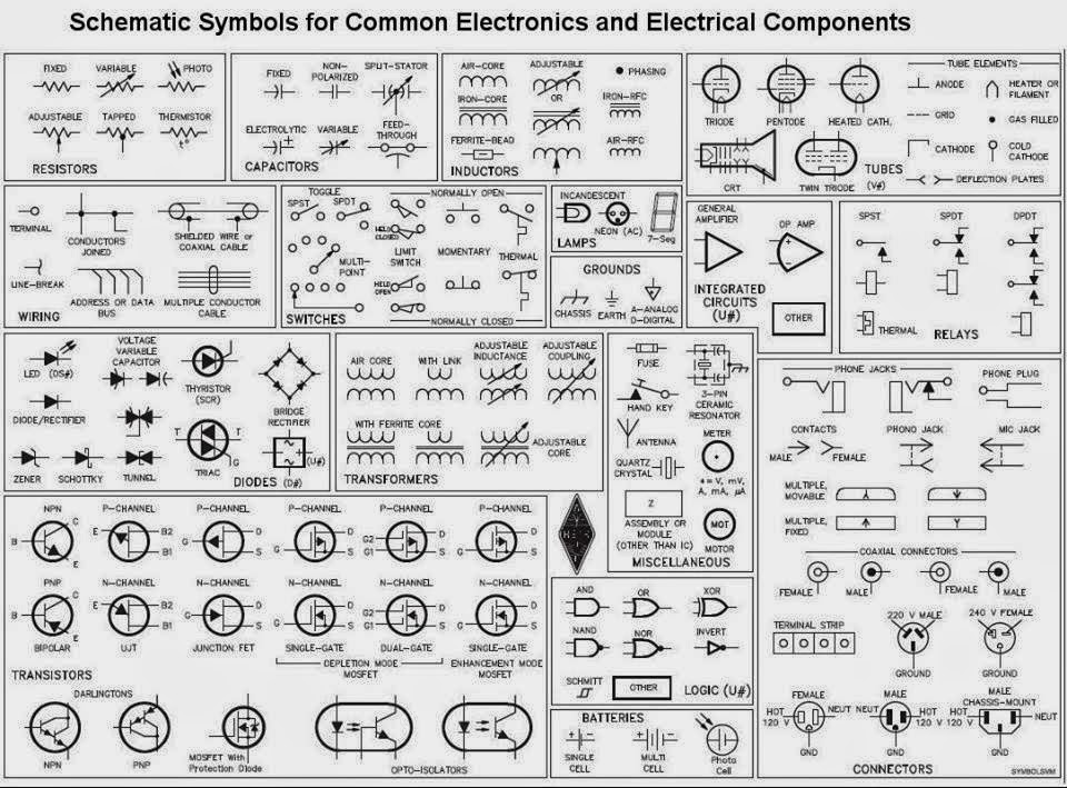
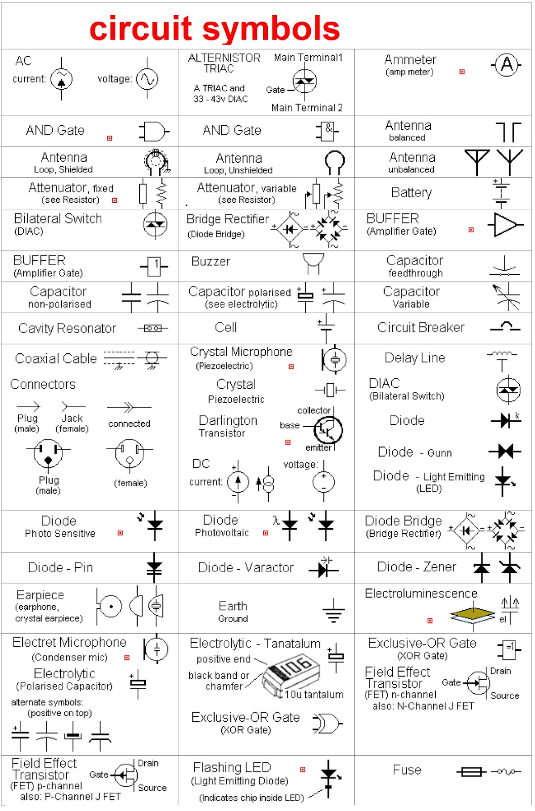
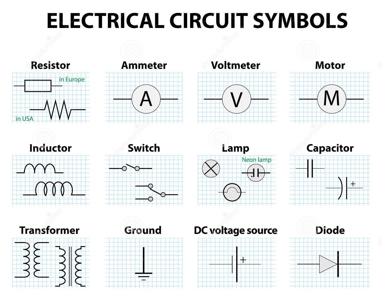
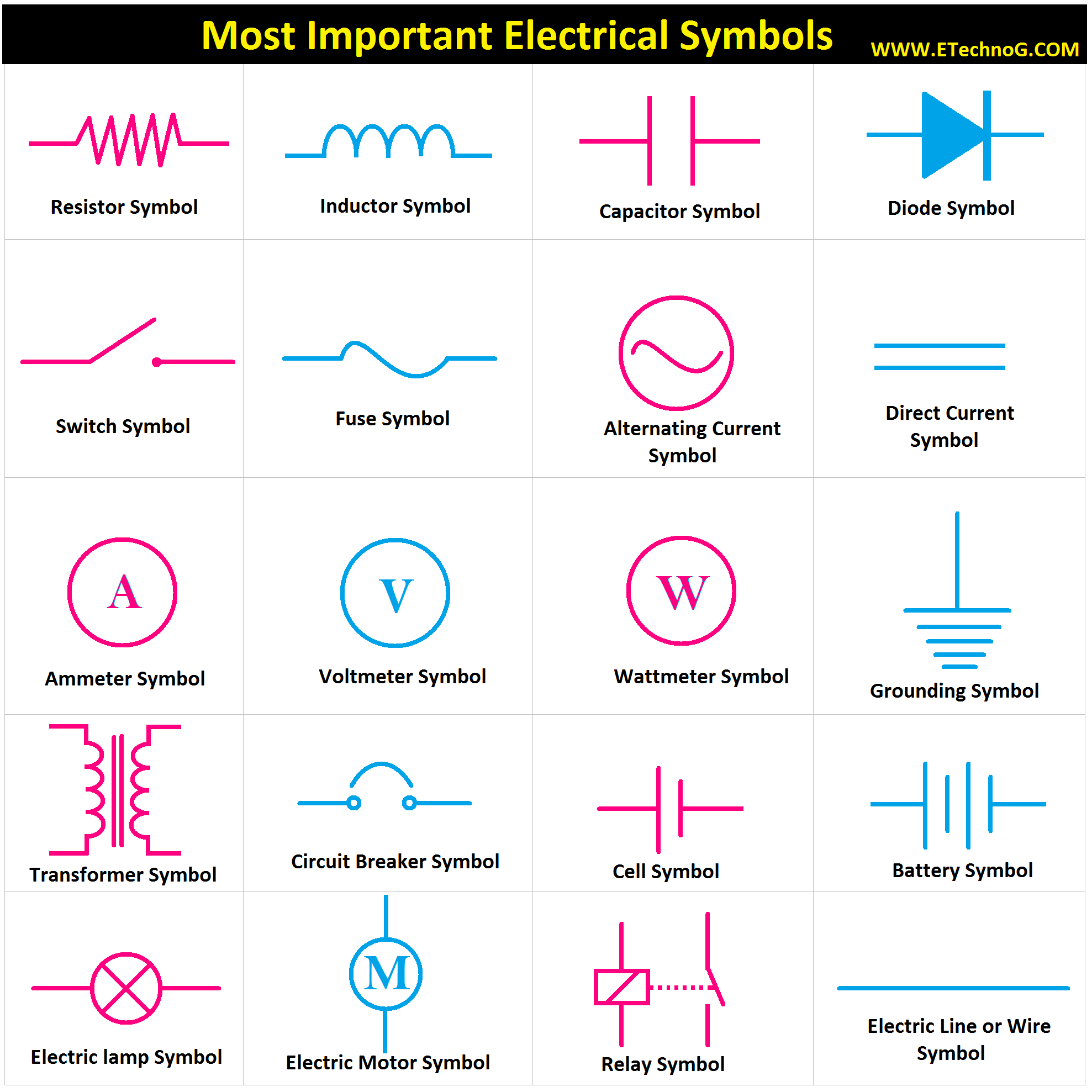
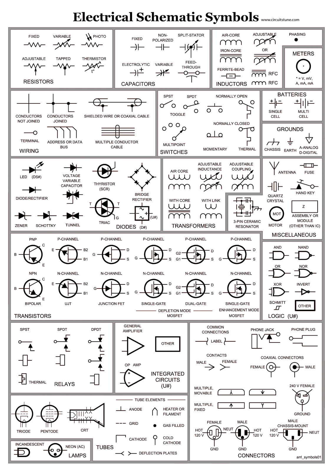
A resistor, represented by a zigzag line, controls current flow. A capacitor, depicted by two parallel lines, stores electrical charge. A diode, symbolized by an arrow pointing towards a line, allows current to flow in only one direction. These are just a few examples of the many symbols used in electrical diagrams. Understanding these symbols is like learning the alphabet of electronics, opening the door to reading and understanding circuit diagrams.
Three key benefits of standardized electronic symbols include enhanced communication, simplified design, and efficient troubleshooting. For instance, an engineer in Japan can easily understand a circuit diagram designed by an engineer in Germany, facilitating global collaboration. The simplified representation of complex components allows for quicker design iterations, saving valuable time and resources. Finally, during troubleshooting, standardized symbols allow technicians to quickly identify faulty components, reducing downtime and repair costs.
Advantages and Disadvantages of Standardized Electrical Symbols
| Advantages | Disadvantages |
|---|---|
| Universal understanding | Requires initial learning |
| Simplified communication | Can be ambiguous if not used correctly |
| Efficient design and troubleshooting | Constant evolution requires staying updated |
Best Practices for Implementing Electrical Symbols: 1. Use the correct symbol for each component. 2. Ensure symbols are clearly drawn and easily legible. 3. Maintain consistency throughout the diagram. 4. Refer to established standards like those from the IEC. 5. Label symbols clearly where necessary.
Real Examples: 1. Residential wiring diagrams. 2. Automotive electrical systems. 3. Printed circuit board (PCB) layouts. 4. Industrial control systems. 5. Schematic diagrams for electronic devices.
Challenges and Solutions: 1. Keeping up with new symbols – Solution: Regularly consult updated standards. 2. Software compatibility – Solution: Use industry-standard design software. 3. Symbol ambiguity – Solution: Provide clear labeling and annotations.
FAQs: 1. What is the symbol for a ground connection? 2. How do you represent a battery in a circuit diagram? 3. What does the symbol for a transistor look like? 4. Where can I find a comprehensive list of electrical symbols? 5. What is the difference between an electrical and an electronic symbol? 6. How are symbols used in industrial control systems? 7. Are there different standards for electrical symbols in different countries? 8. What software can I use to create circuit diagrams with standard symbols?
Tips and Tricks: Familiarize yourself with common symbols by practicing drawing simple circuits. Use online resources and reference books to learn about less common symbols. When in doubt, always refer to the latest IEC standards.
In conclusion, electrical and electronic symbols are the bedrock of communication in the world of electronics. From simple circuits to complex industrial systems, these symbols provide a concise and universally understood language. They are essential for clear communication, efficient design, and effective troubleshooting. While learning the multitude of symbols can seem daunting at first, the benefits of mastering this symbolic language are immense. Embracing these symbols empowers us to unlock the complexities of electrical systems and harness the power of electricity. By understanding and correctly implementing these symbols, we can build a safer, more efficient, and technologically advanced future. So, take the time to learn these essential symbols – it's an investment that will pay dividends in your understanding and ability to navigate the electrical world around us. Start exploring, and you'll discover a fascinating language hidden in plain sight, waiting to be decoded.
Citric acid disposal the eco friendly guide
Unraveling the mystery the function of elephant wrinkles
Obsessed with the moon you need to know when its rising

.jpg)

