Ever wondered how those intricate air-powered systems in factories and machines work? The secret lies in understanding pneumatic schematic diagrams, the blueprints of pneumatic systems. These diagrams use a standardized set of symbols to represent various components, allowing engineers and technicians to design, analyze, and troubleshoot these systems efficiently.
Pneumatic schematic diagrams are more than just drawings; they are a universal language for communicating complex pneumatic designs. They provide a clear and concise representation of the system's layout, components, and connections. Whether you're a seasoned engineer or a curious beginner, grasping the meaning of these symbols is crucial for navigating the world of pneumatics.
The history of pneumatic symbols is intertwined with the development of industrial automation. As pneumatic systems became more complex, the need for a standardized representation arose. Over time, organizations like ISO (International Organization for Standardization) developed standardized symbols, ensuring clear communication and interoperability across different industries and geographical locations.
These standardized pneumatic symbols are essential for several reasons. They facilitate efficient communication between engineers, technicians, and operators, reducing the risk of misinterpretations. They also simplify the design process, enabling engineers to visualize and optimize the system's performance. Furthermore, these symbols play a vital role in troubleshooting, as they help identify faulty components and connections.
One of the main challenges related to pneumatic schematic diagrams is ensuring everyone involved understands the symbols. Misinterpreting a symbol can lead to design errors, improper installation, and system malfunctions. Therefore, proper training and access to updated symbol libraries are crucial for accurate interpretation and implementation of pneumatic system designs.
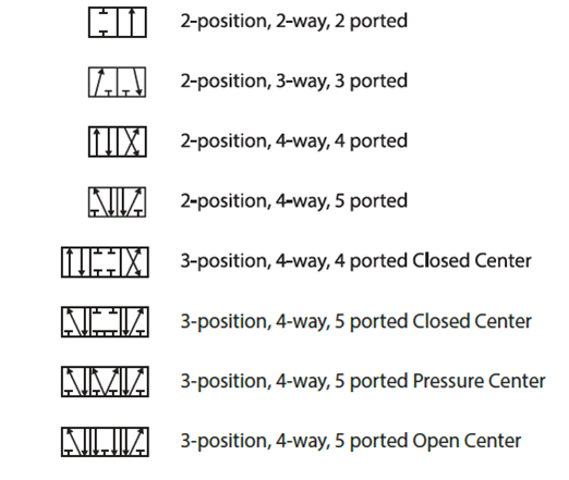
A simple example of a pneumatic symbol is the one for a directional control valve. This symbol typically resembles a box with arrows indicating the flow paths of compressed air. Different configurations of arrows represent different valve functions, such as directing air to extend or retract a cylinder.
One benefit of using pneumatic diagrams is improved troubleshooting. By tracing the flow of air through the symbols, technicians can quickly identify blockages, leaks, or faulty components.
Another advantage is simplified design. The symbols provide a visual language that allows engineers to easily plan and optimize the layout of pneumatic systems.
Clear communication is a third key benefit. The standardized symbols ensure that everyone involved in the project, from designers to operators, understands the system's functionality.
A successful implementation of a pneumatic system starts with a well-designed schematic diagram. This diagram serves as a roadmap for the entire project, guiding the selection, installation, and operation of components.
Advantages and Disadvantages of Pneumatic Schematic Diagram Symbols
| Advantages | Disadvantages |
|---|---|
| Clear Communication | Requires Training |
| Simplified Design | Potential for Misinterpretation |
| Efficient Troubleshooting | Keeping up with Standard Updates |
Best Practices for Implementing Pneumatic Schematic Diagrams:
1. Adhere to ISO standards: Use the latest ISO symbols for consistency and clarity.
2. Maintain clear labeling: Label all components and connections for easy identification.
3. Use a consistent scale: Ensure the diagram is drawn to scale for accurate representation.
4. Provide a legend: Include a legend explaining all symbols used in the diagram.
5. Regularly review and update: Keep the diagram up-to-date with any system modifications.
FAQ:
1. What is the symbol for a compressor? - A circle with a diagonal line.
2. What does a triangle represent in a pneumatic diagram? - Often a flow direction.
3. How is a cylinder represented? - A rectangle with a piston rod.
4. What is the symbol for a pressure regulator? - Usually a symbol resembling a valve with an adjustable spring.
5. How do I represent a filter? - Often a symbol resembling a trap with a filter element.
6. What is the significance of using different line thicknesses? - Can represent different pipe sizes or flow rates.
7. Where can I find a comprehensive list of pneumatic symbols? - ISO standards and online resources.
8. Are there software tools for creating pneumatic diagrams? - Yes, several CAD and specialized software packages exist.
Tips and Tricks:
Use color-coding to differentiate different parts of the system.
In conclusion, pneumatic schematic diagram symbols are the cornerstone of pneumatic system design, analysis, and maintenance. They provide a universal language that bridges the gap between concept and reality. By understanding these symbols, engineers and technicians can effectively communicate designs, troubleshoot problems, and ensure the smooth operation of complex pneumatic systems. The benefits of utilizing standardized symbols, including improved communication, streamlined design processes, and efficient troubleshooting, far outweigh the challenges. Embracing these symbols empowers professionals to harness the full potential of pneumatics in various applications. As technology continues to evolve, staying updated with the latest standards and best practices for utilizing pneumatic schematic diagrams is crucial for success in the field of automation and industrial control. Take the time to learn and master these symbols – it's an investment that will pay dividends in the long run.
Salems secret marketplace unlocking craigslist salem oregon
Unlocking the anglo saxon world exploring old english on wikipedia
Behr sandy clay and silky white a perfect color combination


